




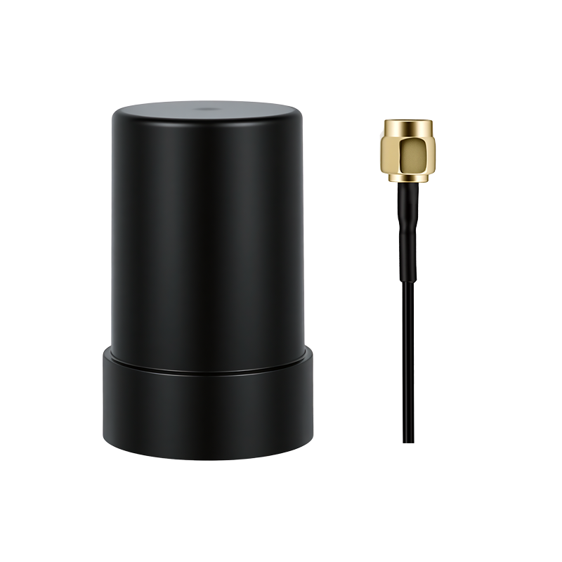
On a drone, the antenna is the cheapest part of the positioning chain and the one most likely to decide whether the whole system works. If you take one line away from this page: where you mount the antenna usually changes real-world accuracy more than a few decibels of gain ever will. The rest is how we would explain that to a team bringing up a new airframe.
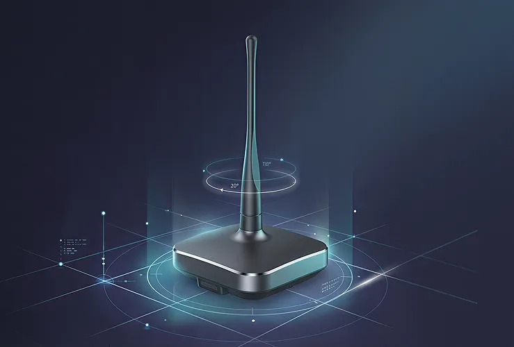
What a UAV Helix Antenna Actually Buys You
GNSS signals arrive right-hand circularly polarised. A helical element is circularly polarised by construction, which is why it became the default for aircraft: as the airframe pitches, rolls and banks, it keeps receiving, where a linearly polarised one would fade in and out with orientation.
The second reason is weight: with its low-noise amplifier, a helical element lands somewhere between roughly 10 g and 30 g depending on diameter. The third is low-elevation reception — mapping and inspection work is often done where satellites sit low over terrain or buildings, and a helical pattern keeps more usable signal there than a compact patch.
What it does not buy you is phase-centre stability. A helix is a compromise antenna, and we say that plainly: for a survey base station or a deformation monitoring installation you want a choke-ring or geodetic antenna instead. The helix wins on weight and attitude tolerance and gives up something in phase-centre consistency. Knowing which of those you need is most of the decision.
Gain Is the Number Everyone Quotes First — and the One That Misleads
Teams compare LNA gain figures and stop there. In practice, anything between roughly 28 dB and 37 dB is workable; what separates a good installation from a bad one is noise figure, linearity, and whether the amplifier is being saturated by something on your own aircraft.
Two things we watch for. A high LNA gain next to a high-power video transmitter can compress the front end — the receiver goes deaf not because the antenna is bad but because it is being shouted at. And gain quoted at zenith tells you nothing about 10° elevation, which is where a drone in a valley actually lives.
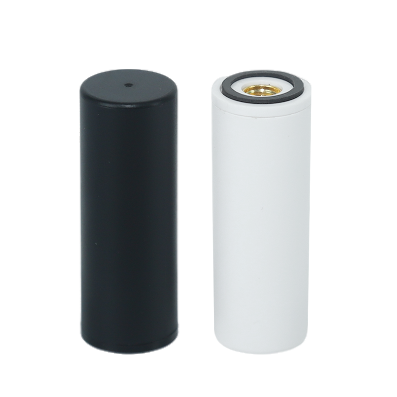
JS-HAC18A-F — Lightest
- Net weight 10.8 g; Φ18 × 50.8 mm
- LNA gain 33 ±2 dB; noise figure ≤2 dB
- Supply 2.8–3.3 V DC; current ≤30 mA
- IP65 with tightened SMA; −30°C to +70°C
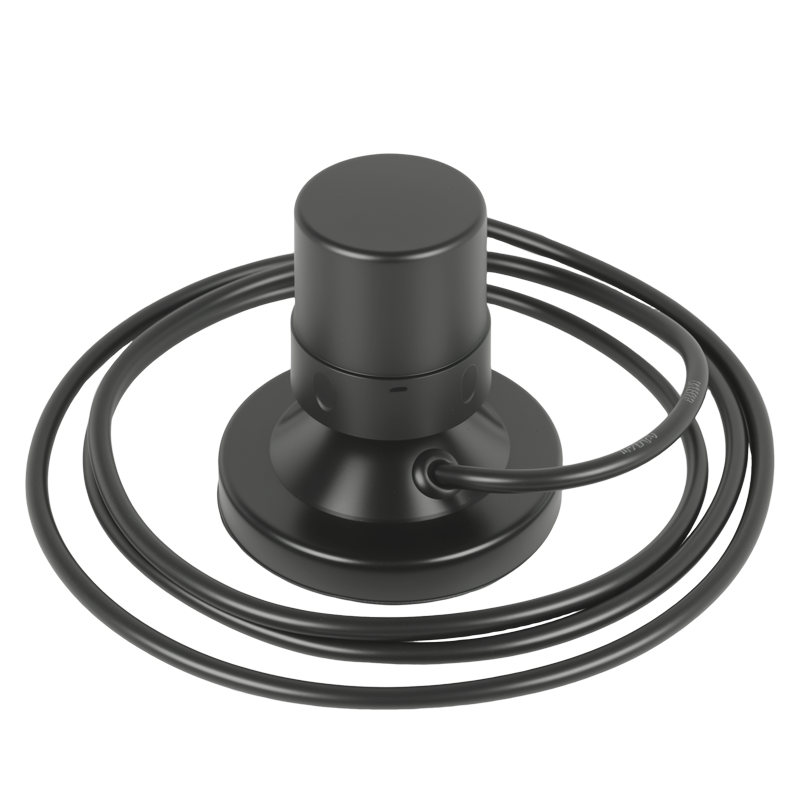
JS-HAC42A-F — Highest Gain
- Net weight 27.3 g; Φ44.8 × 42 mm
- LNA gain 37 ±3 dB; VSWR ≤2.0
- Screw-fixing provision; standard SMA, plug-and-play
- IP65 with tightened SMA; −30°C to +70°C
Those two are the ends of our own range, and the spread is instructive: about 16 g and 4 dB separate them, and the diameter roughly doubles. On a 7-inch racer that is the whole payload budget; on a mapping quad carrying a 1 kg camera it is noise. In between sits a 16.7 g version at 28 ±3 dB, and JS-HAC41A covers platforms without a clean 3.3 V rail — 3.3 V to 12 V supply, peak in-band gain at least 4 dBi.
| Model | Weight | Size | LNA gain | Supply |
|---|---|---|---|---|
| JS-HAC18A-F | 10.8 g | Φ18 × 50.8 mm | 33 ±2 dB | 2.8–3.3 V, ≤30 mA |
| JS-HAC27A-D2 | 16.7 g | Φ28.2 × H59.3 mm | 28 ±3 dB | 2.8–3.3 V |
| JS-HAC42A-F | 27.3 g | Φ44.8 × 42 mm | 37 ±3 dB | Standard SMA, no tuning |
Axial Ratio: The Spec Most Teams Skip
Axial ratio measures how purely circular the polarisation actually is. An ideal circularly polarised antenna has an axial ratio of 1 (0 dB); real ones do not, and the error shows up as a polarisation mismatch loss of up to about 3 dB in the worst case.
The reason it matters on a drone is attitude. A poor axial ratio does not just cost you signal — it makes the level vary with orientation, and that modulation turns into noisy carrier phase and an RTK solution that drops out of fixed as the aircraft banks. Teams then blame the receiver.
Our habit is to ask for the axial ratio across elevation angle, not the zenith value, because a single number at zenith hides exactly the behaviour that bites you in flight. If a supplier will only give you one number, treat it as a reason to keep testing rather than as an answer. The same caution applies to what high gain actually means when it is quoted without conditions.
Where to Mount It: The Decision That Outranks Gain
Get four things right and a modest antenna will outperform an expensive one fitted badly.
- Separation from transmitters. Video and telemetry links are the usual offenders. Every doubling of separation buys real attenuation — keep the GNSS element away from the video transmitter, and never run its coax bundled along a power lead.
- Sky view, not aesthetics. The element needs to see above the horizon in all directions. Mounting it low, where the battery or the gimbal blocks part of the sky, costs you satellites exactly when the aircraft banks.
- Ground plane. A helical element expects a conducting ground plane. Carbon fibre is conductive enough to detune and to shield, and too resistive to behave like one — so give the antenna a metallic ground plane of its own rather than trusting the plate it is bolted to.
- Fix the lever arm. Under RTK or dual-antenna heading, the offset between the antenna phase centre and the IMU has to be measured and held. A mount that flexes between flights corrupts it, and the symptom looks like a calibration problem.
Vibration isolation matters less than rigid, repeatable mounting, and the IP rating is conditional on the mating connector being tightened rather than merely fitted.
Four Mistakes We See Teams Make
1. Specifying on LNA gain alone. The highest-gain part on the shelf can perform worst on a machine carrying its own 5.8 GHz video link, because the front end is being compressed. Measure, do not assume.
2. Mounting under a carbon plate. We see this often on sleek airframes where the antenna is hidden for looks. It costs signal and it detunes the element.
3. Treating the helix as a survey antenna. It is not. For a fixed base station or long-term monitoring, phase-centre stability rules it out — see how to select a GNSS antenna.
4. Remounting between test flights. If the antenna moves between validation and production, the result no longer describes the product.
How to Check It on Your Own Airframe
Three checks, none of which need a chamber:
- Static, powered, rotors turning. Log carrier-to-noise ratio for every tracked satellite with the electronics idling, then again with motors spinning and the video link transmitting. A drop of more than a few dB points at self-interference, not at the antenna.
- Hover and bank. Watch whether signal levels and fix status change with attitude. Variation with bank angle is the axial ratio and sky-view problem showing itself.
- Fly the same line twice. Compare the two passes for track repeatability and for the proportion of time in a fixed RTK solution. A single accuracy number tells you almost nothing; repeatability tells you whether the installation is sound.
Questions Buyers Ask Most Often
Can one antenna serve both normal navigation and RTK?
Usually yes on the reception side, but the requirement differs. RTK cares about phase-centre stability and consistent carrier phase through manoeuvres — where a lightweight helix is a compromise, though the sensible one when weight binds. For a fixed reference receiver, choose a different type.
Does a bigger antenna always position better?
No. More aperture generally helps low-elevation signal and consistency, but it costs payload, drag and mounting space, and on a small airframe those costs can outweigh the benefit. We size the antenna to the mission before we size it to the spec sheet.
Where exactly should it go on a quadcopter?
Top of the frame, on a proper metallic ground plane, as far from the video transmitter as the airframe allows, with the coax routed away from power wiring and secured so it cannot shift between flights.
Do I need a helical antenna for a mapping drone?
If the aircraft must hold an RTK fixed solution while manoeuvring, you need full-constellation, full-band coverage and a mount you can repeat; a helix is the usual way to get that without carrying survey-antenna weight. The receiver side matters equally — the integration detail is covered in RTK module for drone integration.
Still deciding where the antenna goes?
Send us the airframe photos, the transmitter layout and the accuracy target. We will tell you whether the constraint is the antenna, the mount, or the receiver — and if it is the mount, we will say so instead of selling you a different part.
One last practical point: buy one spare and keep the mounting jig. The fastest way to lose a week is to find in flight testing that the antenna sat three centimetres from the video link, with no way to reproduce the geometry. Read the full UAV helix antenna range before you commit to a mount — diameter and weight steps are what constrain the layout.
.png?imageMogr2/format/webp)
.png?imageMogr2/format/webp)
.png?imageMogr2/format/webp)
.png?imageMogr2/format/webp)