





If you are specifying an RTK GNSS module for a drone, a robot, a tracker or a survey handheld, the accuracy figure on page one of the datasheet is the least useful number on it. Every serious module in this class advertises centimetre-level RTK. What separates the parts that hold a fix in your build from the parts that do not is whether the module can reach and keep a fixed solution under the conditions your product actually operates in — partial sky view, a vibrating frame, a shared power rail, a correction link that drops for a few seconds.
This guide follows the order engineers usually hit these decisions: what the accuracy claim really means, which six specifications decide the choice, how to match a module to a platform type, and what to verify before you commit the design to a PCB.
What "Centimetre-Level RTK" Actually Promises
How accurate is an RTK GNSS module in real use?
An RTK module outputs a position solution, and the quality of that solution is a state, not a fixed property. The receiver reports which state it is in. Design against the state, not against the headline number:
| Solution state | Horizontal accuracy | How to use it |
|---|---|---|
| Single-point (no corrections) | Metre level | Fine for asset location, useless for guidance or stakeout |
| DGPS / code differential | Sub-metre | A fallback, not a design target |
| RTK float | Decimetre level | Treat as "not fixed yet" — do not let control logic consume it |
| RTK fixed | Centimetre level | The only state your accuracy spec should quote |
The practical rule: your firmware should read the solution state from the NMEA stream and gate any precision-dependent behaviour on it. A module that reports fixed 95% of the time and float for the remaining 5% is a very different product from one that reports fixed 60% of the time — even though both quote the same centimetre figure. Ask vendors for the fixed rate under defined sky conditions, not just the accuracy at fix.
Why the "+1 ppm" term matters more than the headline figure
RTK accuracy specifications carry a distance-dependent term. A rating written as 1.0 cm + 1 ppm means 1 cm of fixed error plus 1 mm for every kilometre of baseline between rover and reference station. At a 10 km baseline, that second term adds about 1 cm; at 30 km, about 3 cm. JUMPSTAR's own module documentation states the same relationship in plainer language — accuracy degrades by roughly 1 cm for every 10 km away from the base station.
The consequence for design: if your product works across a wide area, the baseline is part of your accuracy budget, not an environment detail. Localising the reference station, or using a dense network correction service, buys back more real accuracy than stepping up to a more expensive module.
Six Specifications That Decide the Choice
Most RTK module comparisons get stuck on accuracy because it is the easiest number to find. These six decide whether the part survives contact with your mechanical, electrical and production constraints:
| Specification | The question to ask | The trade-off you are making |
|---|---|---|
| Bands and constellations | Single-band L1, or L1+L5 / multi-constellation? | More bands cost more current and BOM, but hold fix far better with partial sky |
| Size and power | What board area and current budget exist? | Smallest parts run lowest current, but often integrate less RF front-end |
| Interfaces | How do corrections get in and positions get out? | A second UART dedicated to RTCM avoids protocol contention |
| Antenna integration | Integrated antenna, or external via RF connector? | Integrated removes RF layout work; external allows placement and gain choice |
| Time to first fix | How long after power-on until fixed? | Fast initialisation matters for stop-and-go and frequent power cycling |
| Update rate | 1 Hz, 10 Hz, or 20 Hz? | Higher rates need faster correction delivery and more host bandwidth |
Do I need single-band or dual-band?
Judge this by sky view, not by ambition. If the antenna sees most of the sky — open field, high-altitude UAV, marine — a well-implemented single-band L1 module reaches a fixed solution reliably and costs less in both parts and current. If the product works beside buildings, under tree canopy, or close to reflecting surfaces, the second band earns its cost: it gives the receiver an independent observable to resolve ambiguities with, and it shortens the time spent in float.
A useful shortcut: count how often your device will be denied an open sky. A survey rover used in fields is a single-band candidate. A delivery robot working along building frontage is not.
How much board space and power can I give it?
RTK modules in this class span an order of magnitude in both dimensions. The smallest are around 16 × 12 mm and run at roughly 20 mA; larger integrated-antenna parts occupy 40 mm-class footprints and draw 100–220 mA. Both are legitimate — the question is which constraint is binding on your product.
For a battery-powered tracker that must last weeks, the low-current part is the only real option and you design the antenna around it. For a mains-powered or vehicle-powered device, current is nearly free and you should spend it on more bands and a better front-end.
Which interface carries corrections, and which carries position?
Under-specifying this is one of the most common integration failures. An RTK module has to do two things at once: emit position output (NMEA or a binary protocol) to your host, and accept correction input (RTCM 3.x) from a radio, a modem or a network client. On a single UART, those two streams contend unless your host is careful about scheduling and buffering.
Modules that expose a second serial port dedicated to RTCM input remove the problem entirely — corrections flow in continuously while the primary port stays free for configuration and position output. If your correction link is a cellular NTRIP client rather than a radio, check that the module's default baud rate on that port is high enough for the RTCM message set you intend to send.
Should the antenna be integrated into the module?
An integrated antenna removes RF trace routing, impedance matching, connector selection and most of the compliance risk from your design. That is a genuine acceleration for teams without RF experience, and for products where the module can sit with a clear view of the sky.
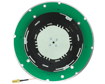
An external antenna wins whenever placement matters: when the module must live inside a metal enclosure, when the antenna needs to be mast-mounted or roof-mounted away from electronics, or when you need a specific gain pattern such as a helical antenna for a UAV that banks during flight. If you go external, budget for the connector, the cable loss and the ground plane — the module datasheet's accuracy figure assumes a competent antenna, not just an antenna.
How quickly does it reach a fixed solution?
Time to first fix is usually quoted for a cold start with good sky. For products that are powered continuously — a base station, a fixed machine — it barely matters. For products that wake, fix and sleep — a tracker reporting once an hour, a handheld used intermittently — it dominates the user experience.
Instant-RTK initialisation technologies bring cold-start fixed solutions down to a few seconds, and that capability is worth paying for precisely in the duty-cycled case. Ask what the number was measured under: a hot start with recent ephemeris and a cold start from a powered-off night are different tests.
What update rate does the platform need?
Static or slow-moving applications are served perfectly by 1 Hz. Anything that moves fast enough for position lag to matter — a UAV at cruise speed, a vehicle at highway speed, a robot arm — wants 10 Hz, and high-dynamic platforms may want 20 Hz.
Two constraints come with the higher rates. First, the correction link has to keep up: a low-bandwidth radio that comfortably feeds 1 Hz corrections may not sustain 10 Hz. Second, not every module supports the top rate on standard firmware — 20 Hz operation on some parts requires specific firmware, so confirm before you design around it.
Matching the RTK GNSS Module to the Platform
The four modules below are arranged by the constraint that typically drives their selection, not by price or accuracy. Each one solves a different engineering problem.
Which RTK module suits a battery-powered tracker or compact device?
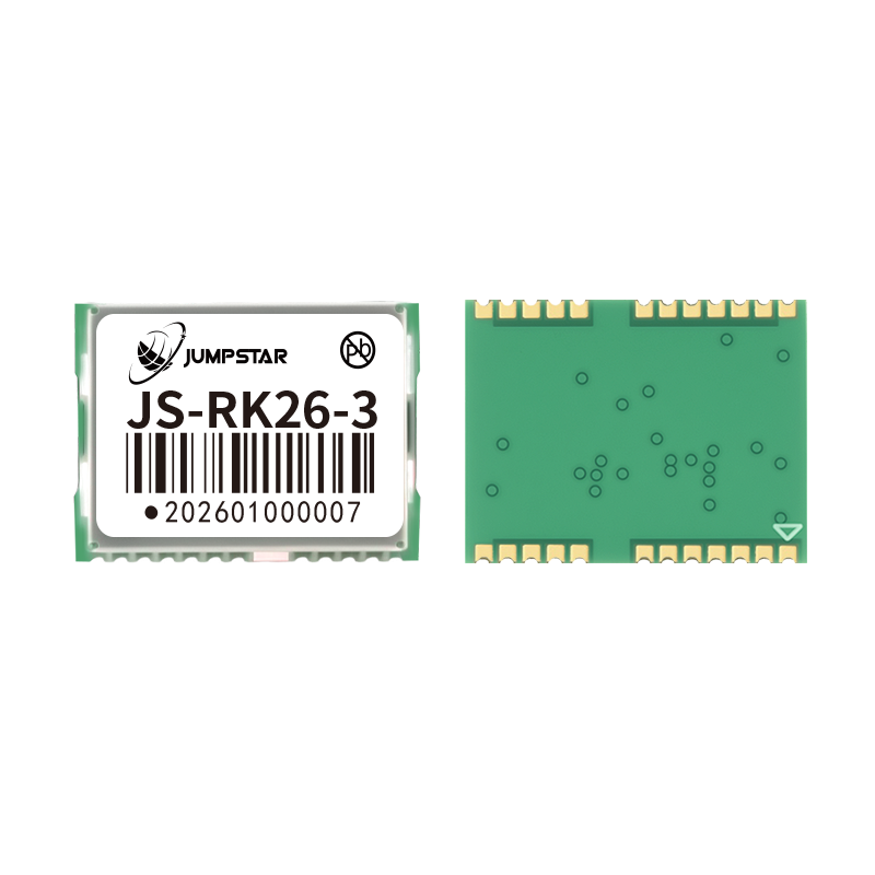
JS-RK26-3 — Ultra-Compact, Ultra-Low Power
- RTK accuracy: 1.0 cm + 1 ppm CEP horizontal, 1.5 cm + 1 ppm CEP vertical
- Footprint 16.2 × 12.2 × 2.3 mm; typical current 20 mA at 3.3 V
- Standby current 14 µA at 3.3 V for long battery life
- Interfaces: UART, I2C, TIMEPULSE (PPS), RESET_N, VCC_RF, VBAT backup
- Works with passive or active antennas (active gain 15–30 dB recommended)
- Operating and storage temperature −40 ℃ to +85 ℃
Choose this when board area and energy are the binding constraints: wearables, asset trackers, sensor pods, anything that must sleep most of the time. Its 14 µA standby is the enabling figure — the module can keep its backup domain alive while the host sleeps, which is what makes fast re-fix possible after a wake event.
Which RTK module fixes fastest and needs no RF design?
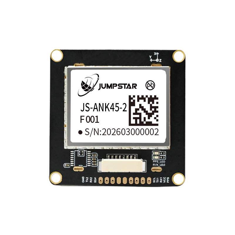
JS-ANK45-2 — Integrated Antenna, Instant RTK
- Instant RTK initialisation: typically reaches fixed solution in under 5 seconds
- Integrated high-gain passive antenna, plus on-board TCXO, LNA, SAW filter and RTC
- 1408 super channels with dedicated anti-interference units
- Interfaces: UART (TTL), RS232 and I2C, with configurable variants
- Magnetometer options: IST8310 default, QMC5883L or VCM5883 selectable
Choose this when your team has no RF layout capability, or when the product power-cycles frequently and cannot wait for a conventional convergence. The integrated antenna, TCXO, LNA, SAW filter and RTC mean the module is close to a drop-in positioning subsystem — the PCB work reduces to power, ground and two signal lines.
Which RTK module suits a product going into volume production?
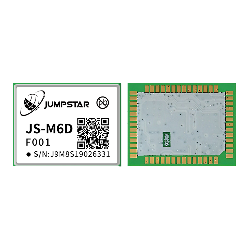
JS-M6D — Full Multi-Band, SMT-Ready
- RTK accuracy: 2 cm + 1 ppm horizontal within a 30 km baseline
- Six frequency points: GPS/QZSS L1+L2, GLONASS G1+G2, BDS B1I+B2I, Galileo E1+E5b
- LGA package 22.0 × 17.0 × 2.4 mm, standard SMT pick-and-place and reflow
- Typical current 105 mA at 3.3 V, peak 130 mA; backup supply 1.8–3.6 V
- Hot start under 1 s, AGNSS-assisted cold start under 3 s
- Built-in antenna open/short detection and antenna power control
Choose this when the design is heading to an SMT line and the product will ship in numbers. Two features matter disproportionately at scale: the LGA package handles standard pick-and-place and reflow without hand assembly, and the antenna open/short detection turns a field failure that would otherwise require bench diagnosis into a flag the host can report.
Which RTK module holds a fix where the sky is partly blocked?
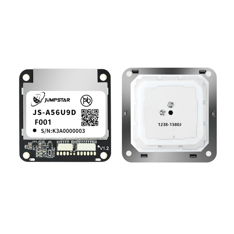
JS-A56U9D — Dual UART, Urban-Canyon Tuning
- Operates in both base station and rover modes
- UART1 for host communication (UBX, NMEA, RTCM); UART2 dedicated to RTCM3 and NMEA
- High-gain integrated antenna — no external RF components required
- Multi-band architecture with concurrent multi-constellation tracking sustains a high fixed rate under partial obstruction
Choose this for vehicles, road-side equipment and urban robots — anywhere the sky view is regularly cut by buildings or foliage. The dedicated second UART is the structural advantage: corrections stream in continuously on their own port while the host port stays available, which is exactly the arrangement an NTRIP client over cellular needs.
What if the platform also needs heading?
A single RTK module gives you a position, not an orientation. If your platform must know which way it is pointing — an AGV docking, a farm machine following a row, a port vehicle aligning to a container — you need two antennas on a known baseline and a receiver that computes the vector between them. That is a different product category: a dual-antenna heading board rather than a single RTK module. JUMPSTAR's heading and positioning boards are built for that job, and the accuracy you get is governed by baseline length and mounting quality far more than by the receiver itself.
Integration Checks Before You Commit
Four questions tend to surface late, when changing the module is expensive. Ask them before layout:
- Where do corrections come from? A network correction service needs cellular coverage and a data plan; a local base station needs someone to site, power and survey it. Many deployments end up using both, with the local base only where network coverage fails.
- Where does the antenna physically sit? The module's accuracy assumes a clear sky view and a sane ground plane. Metal within a few centimetres of the antenna, a carbon-fibre frame above it, or a battery beside it will all cost you fixed-solution uptime.
- What happens during a correction outage? Decide in advance whether the host falls back to float, to dead-reckoning sensor fusion, or to the last known position. Modules in the dead-reckoning range exist precisely because tunnels and underground parking make this the normal case for vehicles, not the exception.
- How will you verify accuracy in production? Plan the test: a surveyed reference point, a defined observation period, and a recorded fixed rate. Without it, you have no way to tell a module problem from an antenna problem on a returned unit.
Where to Start in the JUMPSTAR Range
JUMPSTAR builds the module, the board and the antenna, so the choice is usually a matter of which constraint is binding rather than which vendor to use. Three entry points cover most projects:
- High-precision RTK modules — centimetre-level parts for survey, machine control, robotics and UAV work.
- Standard-precision modules — the right answer when the application needs location rather than guidance, and current budget dominates.
- RTK positioning boards — integrated boards with antenna and interfaces on one carrier, for teams that want a positioning subsystem instead of a component.
If your accuracy requirement is driven by antenna behaviour rather than receiver capability — phase-centre stability, multipath rejection, gain pattern — start with the GNSS antenna range instead. In marginal-sky applications the antenna choice moves the fixed rate more than the module choice does.
Conclusion
Specifying an RTK GNSS module comes down to four decisions, in this order. First, decide which solution state your product can actually act on — and design the firmware to read that state rather than assume centimetres. Second, identify the binding constraint among size, current, band count, antenna integration, initialisation speed and update rate; a module that wins on the constraint you do not have is a poor trade. Third, confirm the interface plan carries corrections and positions without contention. Fourth, verify that a real product exists to carry the antenna and the correction link you have just specified.
The accuracy figure is the output of those decisions, not the input to them. Teams that work through them in this order end up with a module that holds a fixed solution in the field; teams that start from the datasheet headline usually find the gap during integration, when it is most expensive to close.
.png?imageMogr2/format/webp)
.png?imageMogr2/format/webp)
.png?imageMogr2/format/webp)
.png?imageMogr2/format/webp)