


Cameras and lidar answer one question very well: what is around me. They still do not answer the three questions a vehicle has to answer before it moves — where am I on the map, which way is the body pointing, and how fast am I actually travelling.
That is the job of GNSS IMU wheel speed fusion, and it is the part of the stack that gets the least attention until something goes wrong under a tunnel. This is written from the integration side: what each sensor is authoritative for, where each one quietly fails, and the tests that settle the argument before a programme commits.
GNSS IMU Wheel Speed Fusion: Three Sensors, Three Kinds of Truth
Most teams can describe all three sensors. Fewer can say what each one is the authority on, and that distinction is the difference between a fusion design and three devices wired into the same enclosure.
| Sensor | Authoritative for | Rate | Fails by |
|---|---|---|---|
| GNSS / RTK | Absolute position on the Earth | 1–10 Hz | Losing the sky, or receiving reflections |
| IMU | Rotation rate and specific force | 100–200 Hz | Integrating its own bias into drift |
| Wheel speed | Distance travelled through the tyre | 20–100 Hz on CAN | Reporting rotation when the tyre is slipping |
Read that column by column and the architecture writes itself: one sensor has no drift but no continuity, one has continuity but no reference, one has neither yet measures the ground directly and costs almost nothing.
GNSS: The Only Sensor That Knows Where “Here” Is
GNSS is the only sensor that can tell you where you are without having been there before. Everything else starts from an assumption; GNSS starts from the planet.
With RTK corrections it delivers centimetre-level absolute position, and the mechanism is worth stating plainly because it explains the failure modes later: a reference station at a known coordinate measures the current atmospheric and orbit error, sends it as a correction, and the receiver subtracts it. The correction is only as good as the link that carries it and the sky view at the antenna — which is why RTK against PPK matters for post-processing, but does not help a moving vehicle.
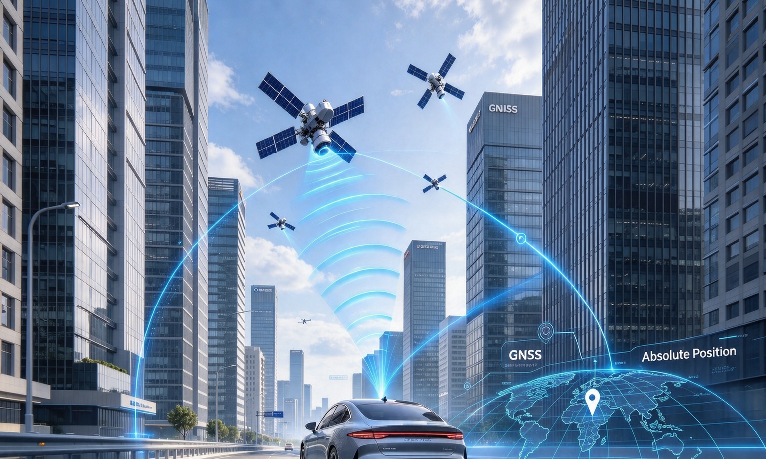
Two properties are routinely misread. The first is rate: 1–10 Hz is normal, so between two fixes the vehicle can travel half a metre at 50 km/h, and something has to fill that gap. The second is that the accuracy figure describes a distribution under stated conditions, not a promise at every instant. In an urban canyon the position you get is often a clean-looking solution computed from reflected signals, which is worse than an obvious loss of fix because nothing in the output warns you. The mechanics of that are covered in mitigating multipath in urban positioning.
IMU: Fast, Smooth, and Wrong Within Seconds
An IMU is the only sensor that knows what the body did in the last ten milliseconds. A gyroscope measures rotation rate, an accelerometer measures specific force, and integrating both gives attitude, then velocity, then a short-term position that is smooth enough to steer on.
It is also the sensor most often over-trusted: its output never looks broken. No dropout, no warning flag, no jump. The track just bends gently away from the road, and the further it goes the more plausible it looks.
The arithmetic is not complicated. A gyroscope with 0.5°/s of residual bias produces 5° of heading error after ten seconds if nothing corrects it, and every metre travelled after that is placed in the wrong direction. The accelerometer has the same problem in a subtler form: it cannot distinguish a sustained acceleration from a tilt, so the filter needs GNSS or wheel speed to tell it which is which.
Datasheets invite confusion because inertial specs come in three units. “Centimetre-level for 3 seconds, metre-level for 10 seconds” is a position statement and can be taken literally. “Error within 5% after 120 seconds of satellite loss” is usually a percentage of distance travelled — 5% of two kilometres is a hundred metres. Both can be true of the same part; they answer different questions.

Wheel Speed: The Cheapest Observer Nobody Owns
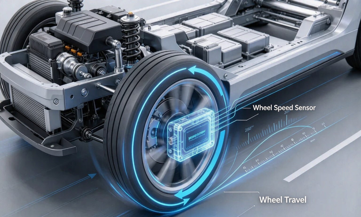
Wheel speed is the only sensor that measures distance through contact with the road — trivial next to centimetre RTK, which is exactly why it gets overlooked.
Its resolution is better than most people assume. With a 48-tooth ring and a 2 m rolling circumference, one pulse is about 4 cm of travel, delivered tens of times per second at walking pace — exactly where GNSS Doppler is weakest. It also gives the filter a scale reference: without an independent distance measurement, a scale error in the inertial solution can only be corrected when GNSS returns.
Its weakness is equally simple. A wheel speed sensor reports rotation, not motion. Under braking, on ice, on gravel, or with a locked wheel, rotation and travel stop agreeing, and the error is not small — it can be the full speed of the vehicle. This is why the useful signal is four wheel speeds, not one averaged vehicle speed: the difference between left and right is what tells the filter that something is slipping.
Then there is the integration reality that decides most projects. On a production vehicle, the four wheel speeds already exist on the chassis bus, published by the ABS or ESC controller. They do not live in the GNSS receiver, and a GNSS+INS module — ours included — does not read them. The wheel-speed leg is joined at the fusion layer or the domain controller, over CAN, with its own latency and its own scaling. If a supplier tells you their module “fuses wheel speed”, the fair question is which connector it arrives on.
How the Three Fit Together in a Real Vehicle
The fusion itself is unglamorous: a filter that predicts with the IMU at high rate, corrects with GNSS when a trustworthy fix arrives, and constrains with wheel speed in between. What changes between vehicles is which sensor carries the solution at any moment.
| Condition | Carrying the solution | What to watch |
|---|---|---|
| Open highway | GNSS, corrected by RTK | Nothing much; this is the easy case |
| Urban canyon | IMU, with GNSS returning intermittently | Reflected fixes that look valid |
| Short tunnel | IMU plus wheel speed | Re-entry error at the portal |
| Long tunnel or underground | Wheel speed, IMU degrading | Scale factor and heading drift |
| Low-speed manoeuvre | Wheel speed plus heading source | Whether heading exists at 0 km/h |
| Low-friction surface | IMU, wheel speed down-weighted | Slip detection, not slip assumption |

What Breaks When One Leg Is Missing
Removing a sensor is the fastest way to see what it was doing; these three signatures are distinct enough to diagnose from a log.
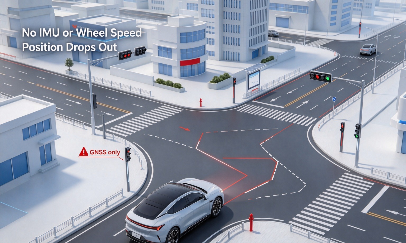
GNSS only: a track made of dots
At 5–10 Hz, the output is a series of positions with nothing in between. In a curve at speed, the gap between epochs is a chord while the chassis travelled an arc. Enter a tunnel and there is no output at all, so the controller stops or hands back — the correct behaviour, and the reason this configuration never ships driverless.
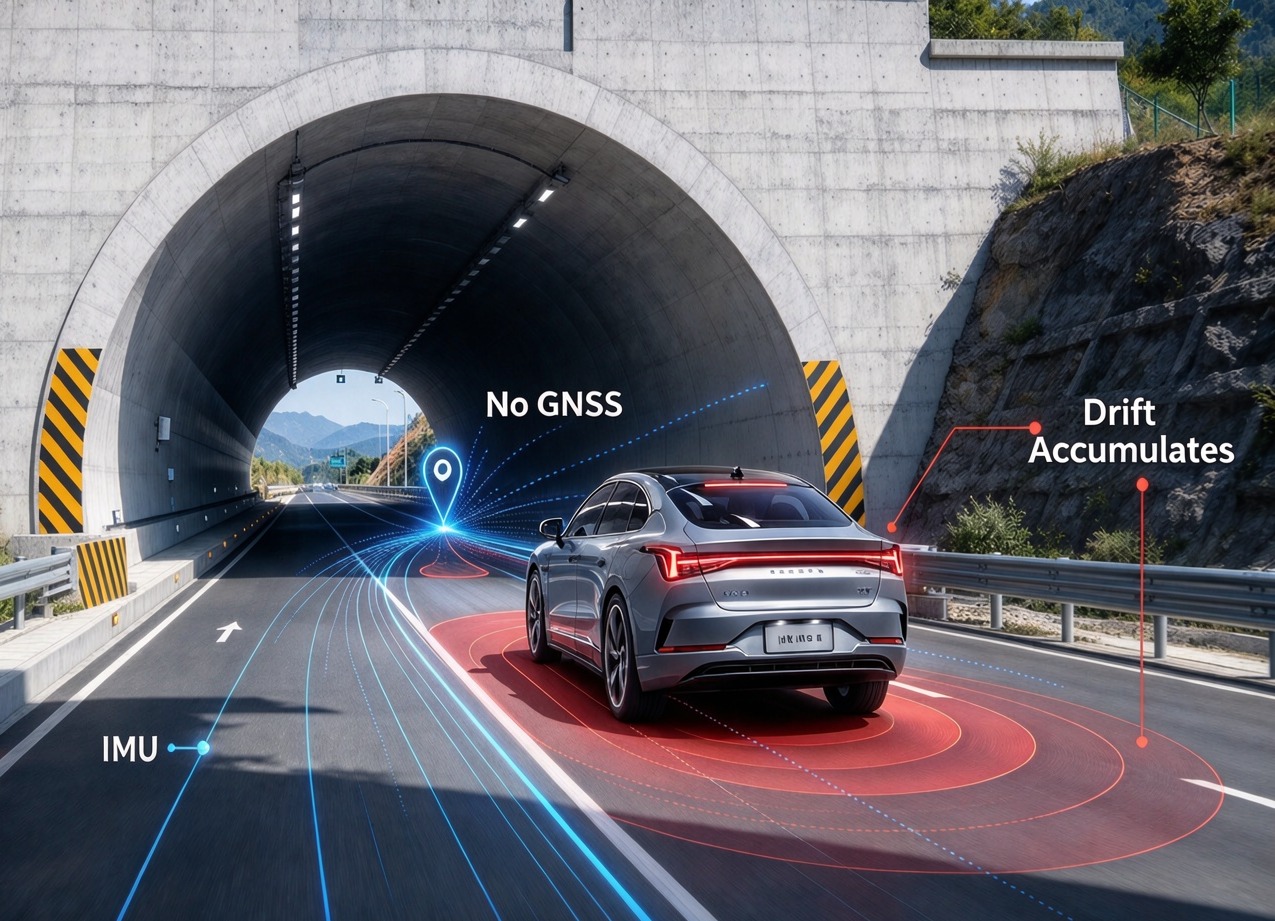
IMU only: a track that bends politely
This is the dangerous one, because it looks like a working system. The position stays smooth, the attitude plausible, and the error grows without a single warning flag. A hundred metres into a tunnel the vehicle may be a lane away from where the system believes it is, and the confidence estimate still looks acceptable.
Wheel speed only: distance without direction
You know how far the wheels turned and nothing else. No heading, no absolute reference, and the moment a tyre breaks traction the distance is wrong by however much the wheel was spinning faster than the ground. It is a good observer and a bad navigator.
Five Integration Mistakes We See Most
None are algorithm problems; all survive a datasheet review and show up on the vehicle.
- The lever arm lives on a drawing, not on the car. If the antenna sits 1.2 m ahead of the rear axle, the system reports the antenna's position, not the axle's, and every controller downstream inherits the offset until someone measures it on the real build.
- Rolling circumference comes from the tyre datasheet. That figure is for an unladen tyre at nominal pressure. Loaded radius, wear and pressure change it by around a percent, which is 10 m per kilometre — enough to walk a vehicle out of its lane in a long tunnel. Measure it: roll the vehicle ten wheel revolutions on a surveyed line.
- One averaged vehicle speed instead of four wheel speeds. Averaging throws away the left-right difference, which is the only cheap slip indicator you have.
- Time alignment is assumed rather than stamped. GNSS arrives at 1 Hz with a PPS edge; wheel speeds arrive on CAN with 10–40 ms of latency. At 20 m/s, 20 ms is 40 cm of error no filter tuning removes.
- The IMU is mounted on something that flexes. A bracket that resonates, or a position near a speaker or a compressor, turns vibration into a false acceleration that integrates into the position. Rigid, metal-to-metal, as close to the axle as the harness allows.
Two Modules That Cover Two of the Three Legs
When a vehicle programme asks us for the GNSS and inertial half of this stack, the choice usually comes down to how much accuracy the tunnel case needs. Both parts below are dual-purpose: RTK when the sky is open, inertial when it is not. Neither claims the third leg — that belongs to the chassis.
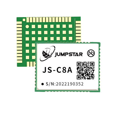
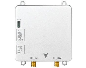
JS-C8A — Multi-Band GNSS + INS
- RTK H ±(8 + 10⁻⁶·D) mm, V ±(15 + 10⁻⁶·D) mm
- 3 s signal loss: cm-level; 10 s: metre-level
- Gyro 250°/s, bias 0.5°/s; accel 4 g, 20 mg
- 22 × 17 × 2.8 mm, BDS/GPS/GLONASS/Galileo
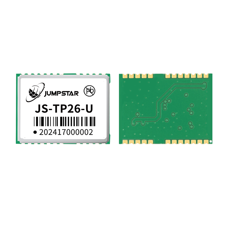
JS-TP26-U — L1+L5 GNSS + INS
- 135 channels (L1: 75 + L5: 60)
- Single-point H 1.0 m (L1+L5) / 2.5 m (L1)
- Six-axis MEMS; no installation orientation restriction
- 16.0 × 12.2 × 2.4 mm, 3 × UART
Two more sit in the same family and get specified when power or update rate dominates: the JS-RK26-U at 18–32 mA with 10 Hz output, and the single-band JS-RP26-U at 20 Hz. All four are listed under dead reckoning positioning modules.
How to Test the Fusion Before You Commit
A bench test proves the module works. It does not prove the three sensors work together on your vehicle. Three measurements do.
- Portal re-entry error. Drive through the tunnel your route actually uses and compare the first fix after the exit with a surveyed point. Record the offset in metres and its direction, not “it stayed locked”. Run it both ways: a heading-dependent error points at the mounting or the gyro.
- Scale factor on a surveyed loop. Time a 200 m straight at constant speed and compare the distance your fusion output reports with the survey. Then repeat on a wet or gravel surface. If the error changes with surface, your wheel-speed weighting is too aggressive.
- Raw logs, twenty-four hours static and one urban run. Plot position scatter from the static test, then overlay wheel speeds and GNSS fix status on the urban run. Almost every “mysterious” jump we have been asked about shows up there as a fix that should have been rejected, or a wheel channel disagreeing with its opposite side.
Questions Buyers Ask Most Often
Can one module handle all three sensors?
Not on a road vehicle. A GNSS+INS module covers two legs; wheel speeds are published by the chassis. A module advertising all three invites one question: which connector takes the wheel-speed input?
How long can the IMU really hold centimetres?
About three seconds for a MEMS unit at centimetre level, then metres for a few seconds more. Anything quoted in minutes describes a different quantity — usually a percentage of distance travelled.
Do we need a dual-antenna heading source?
If the stack needs true heading at standstill, in reverse, or during a slow parking manoeuvre, yes. A single antenna gives course over ground, defined only while moving, and never tells you which way the body points. The trade-off is a second antenna, a baseline and a mounting job — covered in dual-antenna RTK heading.
Is wheel speed worth the effort if the IMU is good?
Yes, at the price: it is the cheapest way to bound distance error in long cover, and the only input that works at walking pace. Worth it only per-wheel and time-stamped; an averaged speed on a slow bus adds little beyond what the IMU already knows.
None of this replaces a careful GNSS IMU wheel speed fusion design, but it does make the supplier conversation specific. For the wider system view, GNSS for autonomous vehicles covers the surrounding architecture, and IMU fusion in GNSS-denied environments goes deeper on the filter.
Building a positioning stack for a vehicle?
Tell us the route, the tunnel lengths, the chassis bus and the accuracy the controller needs. We will tell you which two legs a module can carry, and where the third has to come from.
.png?imageMogr2/format/webp)
.png?imageMogr2/format/webp)
.png?imageMogr2/format/webp)
.png?imageMogr2/format/webp)